The first 9 lessons all used Three.js built-in materials (MeshStandardMaterial, MeshBasicMaterial…). This lesson starts writing custom shaders — talking to the GPU directly with GLSL, so gradients, waves, and Fresnel effects are generated entirely by code instead of built-in material presets.
01 Learning Objectives
This lesson focuses on GLSL shader programming fundamentals:
- Understand the structure and execution flow of Vertex / Fragment Shaders
- Master the roles of
gl_Position/gl_FragColor - Distinguish the three variable types:
attribute/uniform/varying - Understand
ShaderMaterialvsRawShaderMaterial - Master coordinate transformations (model → world → view → clip)
02 GLSL Basic Syntax
GLSL is a C-style shading language, slightly different from JS/TS. First, the most common “parts”.
Scalars (single values):
| Type | Description | Example |
|---|---|---|
int | Integer | int a = 1; |
float | Floating point (with decimal) | float f = 1.0; |
bool | Boolean | bool ok = true; |
Vectors (a group of numbers):
| Type | Components | Usage |
|---|---|---|
vec2 | 2 | UV coordinates |
vec3 | 3 | position, normal, RGB color |
vec4 | 4 | homogeneous coordinates, RGBA color |
Vector components can be accessed with xyzw (as coordinates) or rgba (as colors), both equivalent:
vec4 pos   = vec4(1.0, 2.0, 3.0, 1.0);
float pz   = pos.z;      // treat pos as coordinates: xyzw picks the 3rd component → 3.0
vec4 color = vec4(0.5, 0.0, 1.0, 1.0);
float g    = color.g;    // treat color as a color: rgba picks the 2nd component → 0.0 (green channel)
Matrices: mat2 / mat3 / mat4 are 2×2 / 3×3 / 4×4 matrices. This lesson mostly uses mat4: both projectionMatrix and modelViewMatrix are 4×4 transformation matrices.
Constructing vectors:
vec4(1.0)→ all four components are1.0(note:1.0, not1)vec4(vec3(p), 1.0)→ build a 4D vector from a 3D vector + 1 scalar
03 Vertices and Their Data
A vertex is a point in 3D space, the smallest building block of all geometry:
- A triangle = 3 vertices + 3 edges
- A sphere = a mesh of hundreds of vertices (points only, no faces)
- Analogy: vertices are like LEGO bricks; a model is built from a pile of them

Each vertex carries more than just “where it is” — like every student has an info card:
| Data | Type | Plain explanation |
|---|---|---|
position | vec3 | Where this point is (model coordinates) |
normal | vec3 | The point’s “orientation” — direction perpendicular to the surface. Lighting depends on it: facing the light = bright, away = dark |
uv | vec2 | Which spot on the texture this point maps to. A texture is a 2D image; uv uses 0~1 like latitude/longitude on a map |
Key: these three are different for every vertex, and are called attributes. Three.js passes them in automatically from geometry, and the vertex shader reads them directly.
04 Three Data Channels: attribute / uniform / varying
Shaders pass data through three “channels”, each one-directional:
| Channel | Plain explanation | Who gets a copy |
|---|---|---|
attribute | Each vertex’s own info card | One per vertex, read by vertex shader |
uniform | A shared blackboard (time, matrices), written once by JS | Shared by all vertices/pixels |
varying | A “note” passed from vertex to fragment, auto-interpolated by GPU | Vertex → fragment, one-way |
varying interpolation: the vertex shader writes a varying value per vertex, and the GPU automatically “fills in the middle values” inside the triangle — every pixel receives the interpolated value. That’s why the vUv the fragment shader sees transitions smoothly instead of holding some vertex’s raw value.
Note the direction: attribute / uniform → vertex shader → varying → fragment shader — one-way downward. The fragment cannot pass data back to the vertex.
How the three channels look in code (complete gradient sphere example):
JS side sets uniforms (the blackboard, globally shared):
const material = new THREE.ShaderMaterial({
  vertexShader: gradientVertexShader,     // vertex shader source (GLSL string)
  fragmentShader: gradientFragmentShader, // fragment shader source (GLSL string)
  uniforms: {
    // uniform = the globally shared "blackboard": JS writes once, all vertices/pixels read the same copy
    uTime: { value: 0 },                             // time driver, updated per frame: material.uniforms.uTime.value = elapsed
    uColorA: { value: new THREE.Color('#ff6b6b') },  // gradient start color
    uColorB: { value: new THREE.Color('#4ecdc4') },  // gradient end color
  },
})
Vertex shader: reads attribute (per-vertex uv), writes varying (for the fragment):
varying vec2 vUv;                 // declare the "note": the name must match the fragment shader
void main() {
  vUv = uv;                       // copy the per-vertex uv (attribute) onto the varying
  // MVP transform, read right to left:
  // vec4(position, 1.0) adds w=1 for homogeneous coords → modelViewMatrix (model→view) → projectionMatrix (view→clip)
  gl_Position = projectionMatrix * modelViewMatrix * vec4(position, 1.0);
}
Fragment shader: reads uniform (blackboard) and varying (interpolated by the GPU):
uniform float uTime;              // time from JS (every pixel reads the same copy)
uniform vec3 uColorA;             // gradient start color
uniform vec3 uColorB;             // gradient end color
varying vec2 vUv;                 // varying from the vertex shader (GPU-interpolated across the triangle)
void main() {
  // Build a sine wave on the UV y-axis that flows over time
  // sin outputs -1~1; ×0.5 +0.5 normalizes to 0~1
  float wave = sin(vUv.y * 6.2831 + uTime) * 0.5 + 0.5;
  // Interpolate between the two colors by wave: wave=0 pure A, wave=1 pure B
  vec3 color = mix(uColorA, uColorB, wave);
  // Output RGBA (each 0~1); alpha=1 means fully opaque
  gl_FragColor = vec4(color, 1.0);
}
The mapping: uv (attribute, per-vertex) → vertex shader assigns to vUv (varying) → GPU interpolates → fragment shader reads it; uTime / uColorA / uColorB (uniforms, one global copy) are passed in from JS and readable by both shaders.
05 Vertex Shader and Rasterization
The GPU pipeline for one frame:
Vertex data → Vertex shader → Rasterization → Fragment shader → Screen
- Vertex shader: runs once per vertex, computes where each vertex ends up
- Rasterization: fills “the triangle formed by vertices” into individual pixels. The vertex shader only computed the corners; rasterization fills the interior with pixels, one position each
- Fragment shader: runs once per pixel, colors that pixel

The two red panels in the pipeline diagram are stage contracts: a programmable stage can only write its own outputs. Writing gl_FragColor (which exists only in the fragment stage) in the vertex shader is a compile error; writing gl_Position in the fragment shader cannot work (the vertex stage has ended, rasterization is done). The data flow is one-way with no reverse channel.
Analogy: the vertex shader builds the skeleton outline, rasterization fills the outline with small cells (pixels), the fragment shader paints each cell.
06 gl_Position — Final Vertex Position
The vertex shader must assign gl_Position, telling the GPU “where this vertex ends up on screen”.
The coordinates pass through a chain of transformations:
Model space →[modelMatrix]→ World space →[viewMatrix]→ View space →[projectionMatrix]→ Clip space
| Variable | Equivalent | Plain explanation |
|---|---|---|
modelMatrix | — | Model→world (object position/rotation/scale) |
viewMatrix | — | World→view (how the camera sees) |
projectionMatrix | — | View→clip (perspective/orthographic) |
modelViewMatrix | viewMatrix × modelMatrix | Precomputed shortcut |
Standard form:
// vec4(position, 1.0): pad the vec3 coordinate with w=1 into a 4D homogeneous vector (matrix math needs 4D)
// Read right to left: first modelViewMatrix (model→view space), then projectionMatrix (view→clip space)
gl_Position = projectionMatrix * modelViewMatrix * vec4(position, 1.0);
07 gl_FragColor — Pixel Color
The fragment shader must assign gl_FragColor, the pixel’s RGBA color (0~1):
gl_FragColor = vec4(r, g, b, a); // each component 0~1: red, green, blue, opacity
08 ShaderMaterial vs RawShaderMaterial
| Feature | ShaderMaterial | RawShaderMaterial |
|---|---|---|
| Built-in uniforms | Auto-injected (projectionMatrix etc.) | Not injected |
| Built-in attributes | Auto-declared (position, uv etc.) | Not declared |
| Precision declaration | Auto-added | Must declare manually |
| Use case | Fast development | Full customization |
ShaderMaterial is more concise (no need to declare built-ins manually); RawShaderMaterial is more flexible (full control over the shader header). Prefer ShaderMaterial for daily development; use RawShaderMaterial only when you need full control over the header (custom precision, int attributes, uniform prefixes).
09 Common GLSL Built-in Functions
| Function | Purpose | Example |
|---|---|---|
mix(a, b, t) | Linear interpolation | mix(red, blue, 0.5) → purple |
sin(x) / cos(x) | Periodic oscillation | Color flow, vertex waves |
pow(x, n) | Power | Fresnel falloff curve |
normalize(v) | Normalize vector | Normals, light directions |
dot(a, b) | Dot product | Lighting, Fresnel |
max(a, b) | Maximum | Guard against negatives |
clamp(x, min, max) | Clamp range | Prevent overflow |
step(edge, x) | Step function | Hard edges |
smoothstep(a, b, x) | Smooth step | Soft edges |
10 GLSL Strong Typing: Why 1 and 1.0 Differ
GLSL is strongly typed; 1 and 1.0 are different types and cannot be mixed:
| Notation | Type | Note |
|---|---|---|
1 | int | Integer |
1.0 | float | Floating point |
vec4(1) | Compile error | int cannot construct a float vector directly |
vec4(1.0) | Valid | float construction |
Rules:
- int can implicitly convert to float (
float x = 1;is legal) - float cannot implicitly convert to int (
int x = 1.0;errors; useint(1.0)) 1.0 + 1is legal (int promotes to float), but>=/==comparisons require matching types- Common errors:
vec4(1), passing anintto afloatuniform
Practical advice: always write constants with a decimal point (like 1.0, 0.5) to avoid type-mismatch compile errors.
11 Implementation Highlights
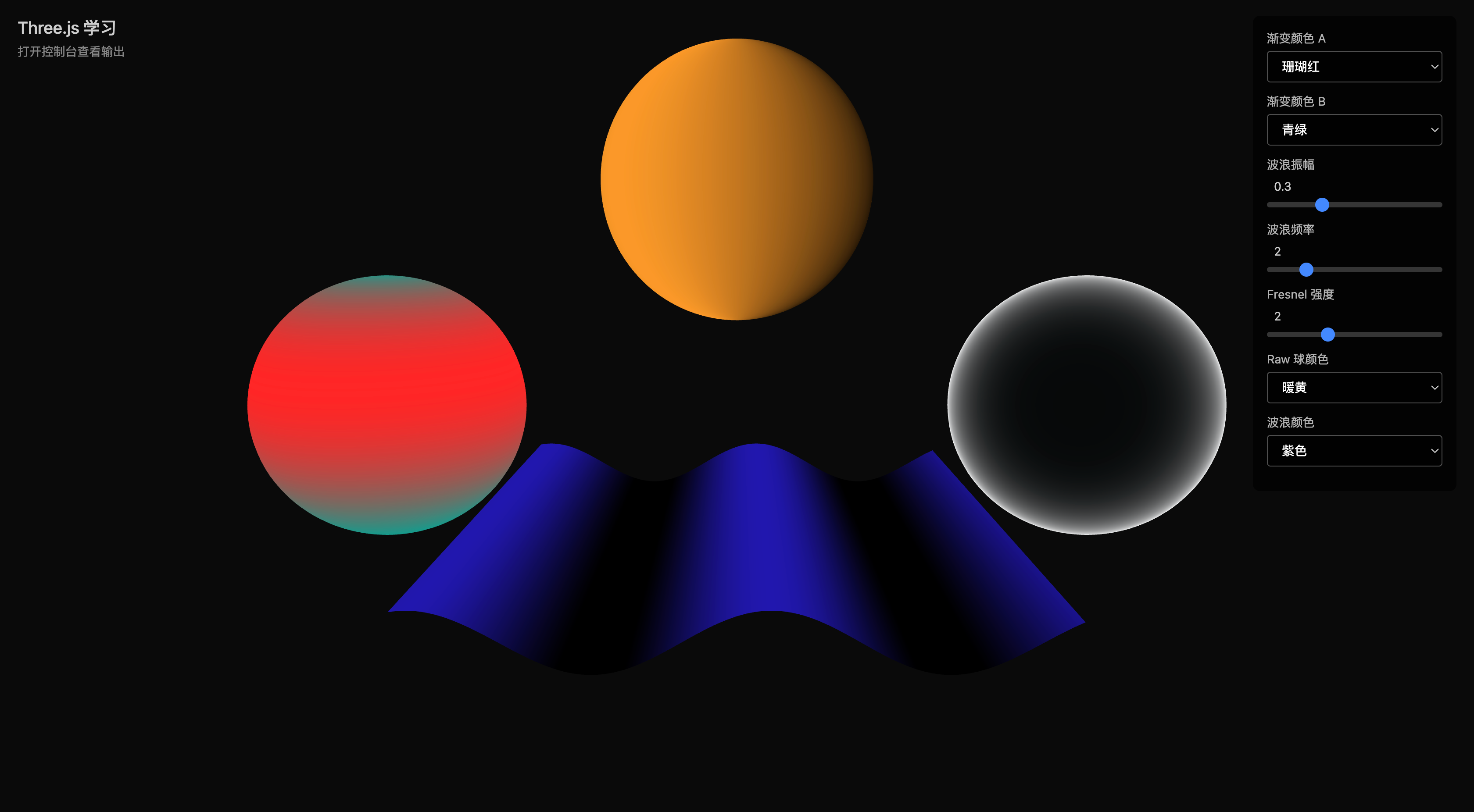
Gradient sphere — basic ShaderMaterial
Demonstrates: uniform for time, varying for UV, mix() for color blending:
// Vertex Shader
varying vec2 vUv;                 // declare the "note" for the fragment stage
void main() {
  vUv = uv;                       // pass UV to the fragment shader
  gl_Position = projectionMatrix * modelViewMatrix * vec4(position, 1.0);
}

// Fragment Shader
uniform float uTime;              // time driver: the wave flows over time
uniform vec3 uColorA;             // gradient start color
uniform vec3 uColorB;             // gradient end color
varying vec2 vUv;                 // UV from the vertex shader (each pixel gets the interpolated value)
void main() {
  // 6.2831 ≈ 2π: one full sine period across the UV y range
  float wave = sin(vUv.y * 6.2831 + uTime) * 0.5 + 0.5;
  vec3 color = mix(uColorA, uColorB, wave);  // wave decides the blend ratio
  gl_FragColor = vec4(color, 1.0);
}
Wave deformation — vertex animation
Demonstrates: modifying position in the vertex shader, normal transformation, diffuse lighting:
// Vertex Shader
uniform float uTime;         // time: drives the wave flowing along X
uniform float uAmplitude;    // amplitude: how high the wave peaks
uniform float uFrequency;    // frequency: how dense the peaks are
varying vec3 vNormal;        // transformed normal, for lighting in the fragment shader
varying float vDisplacement; // this vertex's displacement; the fragment shader can color by it (crests bright, troughs dark)

void main() {
  // Sine wave along the X axis: vertices at different x displace differently, forming ripples at one instant
  float displacement = sin(position.x * uFrequency + uTime) * uAmplitude;
  // Push along the normal: each surface point moves along its own orientation, forming a smooth bulge
  vec3 newPosition = position + normal * displacement;
  // Normals must be transformed with normalMatrix (the inverse-transpose of modelViewMatrix);
  // multiplying modelViewMatrix directly would break the normal's "perpendicularity"
  vNormal = normalMatrix * normal;
  vDisplacement = displacement;
  // Compute the final screen position from the displaced position
  gl_Position = projectionMatrix * modelViewMatrix * vec4(newPosition, 1.0);
}
Fresnel effect — rim glow
Demonstrates: world-space normal transformation, view direction computation, pow() falloff:
// Fragment Shader
uniform vec3 uCameraPosition;   // camera world position (JS syncs camera.position every frame)
uniform float uFresnelPower;    // Fresnel exponent: higher = narrower, sharper rim
varying vec3 vWorldNormal;      // world-space normal from the vertex shader
varying vec3 vWorldPosition;    // world-space position from the vertex shader

void main() {
  // View direction = camera position - surface point, normalized to a unit vector
  vec3 viewDir = normalize(uCameraPosition - vWorldPosition);
  // The interpolated normal may no longer be length 1; re-normalize before any dot product
  vec3 normal = normalize(vWorldNormal);
  // dot(viewDir, normal): near 1 when facing the camera, near 0 when the view grazes the edge
  // max(..., 0.0) guards against negative values on back faces
  // 1 - dot → near 0 head-on (no glow), near 1 at the rim (glow)
  // pow narrows the 0~1 transition, controlling the rim width
  float fresnel = pow(1.0 - max(dot(viewDir, normal), 0.0), uFresnelPower);
  // Add a white glow on top of the base color, scaled by fresnel → a bright rim
  vec3 finalColor = uColor + vec3(1.0) * fresnel;
  gl_FragColor = vec4(finalColor, 1.0);
}
RawShaderMaterial — declaring built-ins manually
Demonstrates: ShaderMaterial “auto-injection” vs RawShaderMaterial “manual declaration”:
// Vertex Shader (unlike ShaderMaterial: precision, attributes, uniforms must be declared manually)
precision highp float;          // precision declaration: ShaderMaterial adds it automatically; Raw requires it by hand

attribute vec3 position;        // built-in attribute: must be declared too
attribute vec2 uv;

uniform mat4 modelViewMatrix;   // built-in uniform: also manual
uniform mat4 projectionMatrix;

varying vec2 vUv;

void main() {
  vUv = uv;
  gl_Position = projectionMatrix * modelViewMatrix * vec4(position, 1.0);
}

// Fragment Shader
precision highp float;          // the fragment shader needs its own precision declaration

uniform float uTime;
uniform vec3 uColor;

varying vec2 vUv;

void main() {
  // Periodic brightness pulse along X
  float pulse = (sin(vUv.x * 6.2831 + uTime) + 1.0) * 0.5;
  gl_FragColor = vec4(uColor * pulse, 1.0);  // pulse acts as a brightness factor, breathing 0~1
}
Creation:
const material = new THREE.RawShaderMaterial({
  vertexShader: rawVertexShader,      // vertex shader source (with all manual declarations)
  fragmentShader: rawFragmentShader,  // fragment shader source
  uniforms: {
    uTime: { value: 0 },                           // time, updated by JS every frame
    uColor: { value: new THREE.Color('#fdcb6e') }, // base color
  },
})
12 Cheat Sheet
| Concept | Description | Key point |
|---|---|---|
| attribute | Per-vertex data | position / normal / uv, vertex shader only |
| uniform | Globally shared data | Time, matrices, colors; readable by both shaders |
| varying | Vertex→fragment transfer | Auto-interpolated during rasterization |
| gl_Position | Vertex shader output | Clip-space coordinates, must be assigned |
| gl_FragColor | Fragment shader output | RGBA color (0~1), must be assigned |
| ShaderMaterial | Three.js wrapper | Auto-injects built-ins and precision |
| RawShaderMaterial | Raw shader | Declare everything manually, full control |
| vec2/vec3/vec4 | Vector types | UV / position / homogeneous coordinates |
| mat4 | 4×4 matrix | Workhorse of MVP transforms |
| Strong typing | 1 ≠ 1.0 | Always write constants with a decimal point |
13 Self-Review
Q1: The standard form is gl_Position = projectionMatrix * modelViewMatrix * vec4(position, 1.0). What happens if the order is flipped to modelViewMatrix * projectionMatrix * vec4(position, 1.0)?
The object disappears, distorts, or flickers — not merely “looks wrong”. Matrix multiplication is not commutative; the rightmost applies first. Flipped, projection transforms to clip space first, then the model-view matrix operates on clip-space coordinates — geometrically meaningless. More critically: projectionMatrix outputs homogeneous clip coordinates (w ≠ 1), and the subsequent modelView multiplication treats w as a position component, breaking the perspective divide.
Follow-up: why does GLSL use column vectors (M * v) instead of row vectors (v * M)? — In a column-vector world it’s M × v; in a row-vector world it’s v × M. GLSL is a column-vector world: matrices on the left, vectors on the right, transformation order read right-to-left (rightmost applies first). OpenGL (GLSL) uses column vectors; DirectX (HLSL) defaults to row vectors — same math, opposite expression.
Q2: A triangle’s three vertices are assigned varying values 1.0, 0.0, 0.0. After rasterization, what value does the fragment shader receive at the triangle’s center?
Center = 1/3. Each vertex has weight 1/3 (barycentric coordinates): 1×1/3 + 0×1/3 + 0×1/3 = 1/3. The value depends only on relative position (barycentric coordinates), not triangle size — a bigger triangle just means higher pixel density and smoother gradients; a smaller one means fewer pixels and “jumpy” transitions (aliasing), but the interpolated value at each position is unchanged. Strictly: the interpolation algorithm itself is size-independent; the observed smoothness difference comes from screen-space sampling density.
Follow-up: what if you compute the varying value directly in the fragment shader instead? — Any “direct computation” in the fragment shader either uses only global uniforms (→ solid color) or screen coordinates (→ doesn’t follow the model). Neither reproduces “a gradient attached to the model surface”. Manually computing barycentric coordinates is theoretically possible but loses the GPU’s hardware perspective-correct interpolation — possible, but shouldn’t be done.
Q3: Why can’t the vertex shader write gl_FragColor, and why can’t the fragment shader write gl_Position?
It’s a compile error, rooted in the hardware division of labor between stages. When the vertex shader runs, pixels don’t exist yet — the vertex stage handles zero-dimensional points and has no idea “which screen pixel”; pixel color only becomes meaningful after rasterization fills the triangle. When the fragment shader runs, the vertex stage has long finished. The GPU is a one-way pipeline with fixed-order data flow and no reverse channel; each programmable stage can only write its own built-in outputs. Violating this, the GLSL compiler reports undeclared identifier during semantic analysis — because gl_FragColor exists only in the fragment shader’s namespace.
Q4: What is the essential difference between uniform and varying? Why do color and height use them separately in the gradient sphere?
A uniform is a globally shared constant (position-independent); a varying is a per-vertex value (needing interpolation for continuous transitions). In the gradient sphere: color uses a uniform — it’s a “globally shared constant” independent of where the pixel sits on the sphere; the height ratio (0~1 scalar) uses a varying — every vertex has a different height, and interpolation between vertices is what forms the continuous transition.
14 Plain-Language Explanations
The GPU rendering pipeline
The vertex shader is the frame builder — working only at a few key nodes (vertices). Rasterization is the floor tiler — filling the enclosed region with small tiles (pixels). The fragment shader is the painter — coloring each tile individually. The three work strictly in order; the painter can never go back and change the frame.
varying interpolation — three buckets of paint
Imagine a sheet of paper shaped like a triangle, with the three corners dipped in red, green, and blue. You don’t paint pixel by pixel with a brush — you dip the corners and let the middle “blend itself”.
That’s what the GPU does: the vertex shader labels the three corners (varying values); during rasterization the GPU checks each pixel’s “position weight” in the triangle (barycentric coordinates) and automatically mixes the three labels by weight. The center’s weight is 1/3, 1/3, 1/3 — a direct average; the closer to a corner, the bigger that corner’s weight and the more the color leans toward it.
Key: this blending happens in screen space (the projected triangle), so if perspective compresses one corner of the triangle, the color transition near it appears “denser” — the same world-space area is squeezed into fewer pixels.
attribute / uniform / varying — the classroom analogy
attribute: every student’s own info card (seat number, name) — one each, all differentuniform: the blackboard — the teacher (JS) writes once, the whole class (all vertices and pixels) sees the same contentvarying: a note passed from vertex to fragment, which the GPU “auto-completes” along the way — three vertices each write a note, and every pixel inside the triangle receives a position-weighted blend of them
Strong typing — 1 vs 1.0
To GLSL, 1 and 1.0 are two different things: 1 is an integer, 1.0 is a float. Like “1 apple” vs “1.0 pounds of apples” — both countable, but different units, and mixing them directly causes trouble. The iron rule for shader constants: always write the decimal point.
15 Resources
This is the 10th note in the Three.js Creation Diary series. Course rating: 9.2/10.