- Instructor: Lingqi Yan | UCSB
- Bilibili: https://www.bilibili.com/video/BV1X7411F744
- Lectures covered: Lecture 19 (Cameras, Lenses and Light Fields)
Note: the previous nine posts kept answering “how do we draw a model into an image” — that is synthesis. This one turns around and asks how an image gets captured. Nearly every part of a camera — lens, aperture, shutter, sensor — maps onto a parameter in a renderer, and effects like depth of field, defocus blur and exposure finally get a physical model.
1 Imaging: Synthesis + Capture
Cameras and lenses are the other half of “imaging” in graphics. Rasterization and ray tracing solve synthesis — generating an image from a model; the camera solves capture — collecting an image from the real world. Both end up at the same place: the irradiance recorded on the sensor plane.
Why does understanding cameras matter? Because it explains why our everyday photos come out blurry, soft or overexposed, and it hands the renderer the physical model behind depth of field, defocus blur and exposure.
What is inside a camera
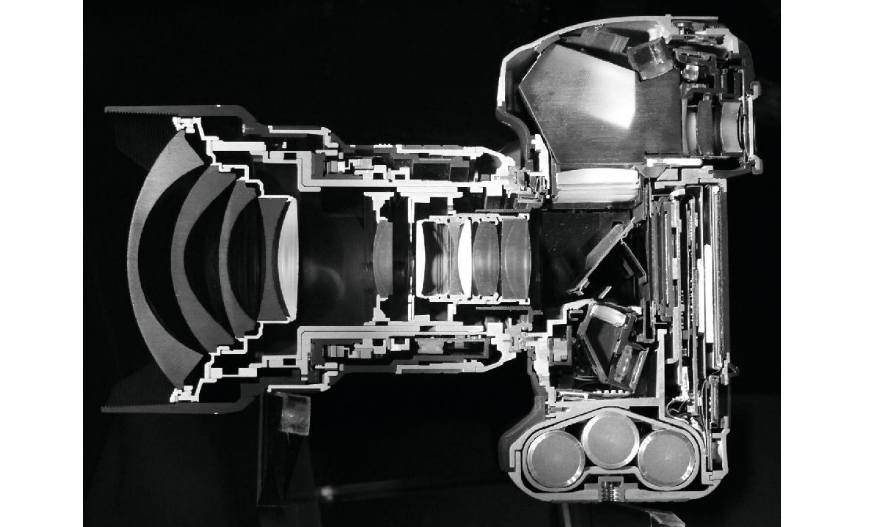
A camera splits into a few parts with clear responsibilities:
| Part | Role |
|---|---|
| Lens | Refocuses light arriving from different directions in the scene to form an image on the sensor |
| Aperture | Controls how much light gets in (and simultaneously determines depth of field) |
| Shutter | Controls how long the sensor is exposed to light |
| Sensor | Accumulates irradiance during the exposure and finally turns it into pixel values |
Pinholes and lenses form images on the sensor
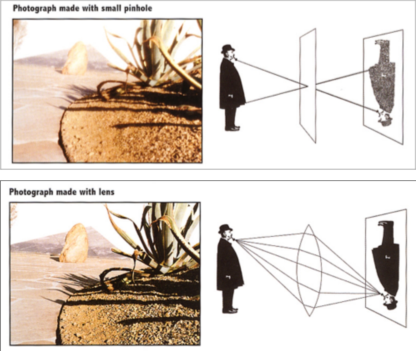
Whether it is a pinhole or a lens, the goal is the same: restrict the ray directions each sensor point can receive, so that light from only a small patch of the scene lands on a single point, and an image corresponding to the scene forms on the sensor.
The shutter and the sensor’s accumulation
The shutter opens for a precise amount of time, exposing the sensor.
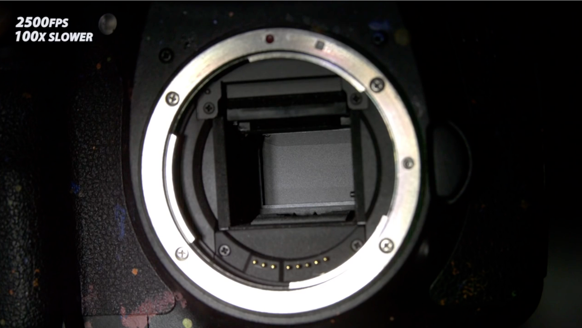
The sensor accumulates irradiance during the exposure — it records “the total light that fell during this interval”, not the light at a single instant.
Why we cannot do without a lens
Remove the lens and keep only a sensor: every sensor point integrates the light emitted by every point on the object, so all pixel values end up roughly the same — you get a uniform grey rather than an image.
The reason is that the sensor records irradiance: irradiance is “the total power per unit area arriving from all directions”, and it inherently throws away directional information. To form an image you must first filter out the direction — which is exactly what a pinhole or a lens does.
Side note: the field of computational imaging really does study lensless cameras, recovering images by computation rather than optics — but that is a separate technical route.
A short history of pinhole imaging
Pinhole image formation is the earliest imaging model humans understood, and it was discovered independently by several civilizations:
| Person | Era |
|---|---|
| Mo Tzu | c. 470–390 BC |
| Aristotle | 384–322 BC |
| Ibn al-Haytham | 965–1040 |
| Shen Kuo | 1031–1095 |
| Roger Bacon | c. 1214–1294 |
| Johannes Kepler | 1571–1630 |
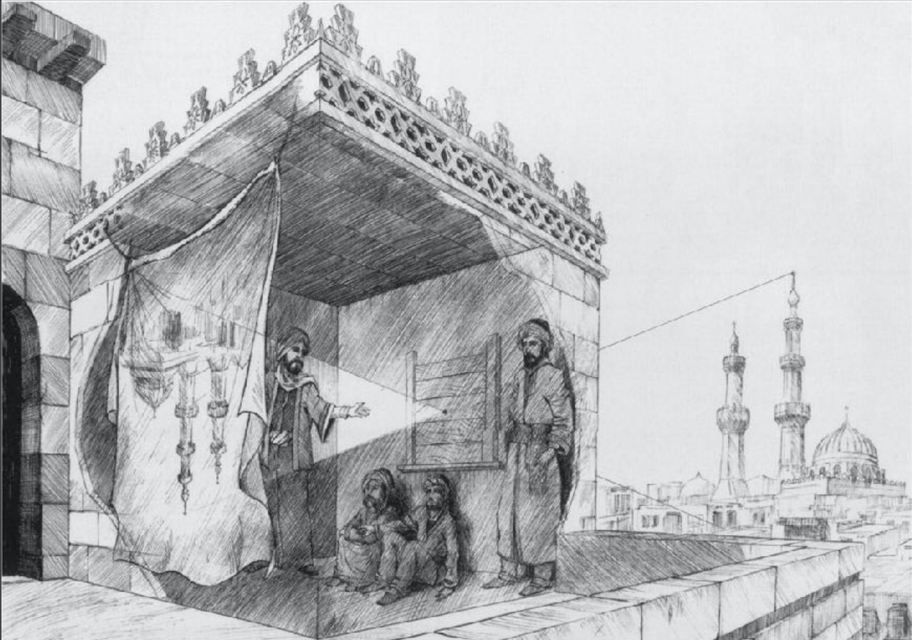
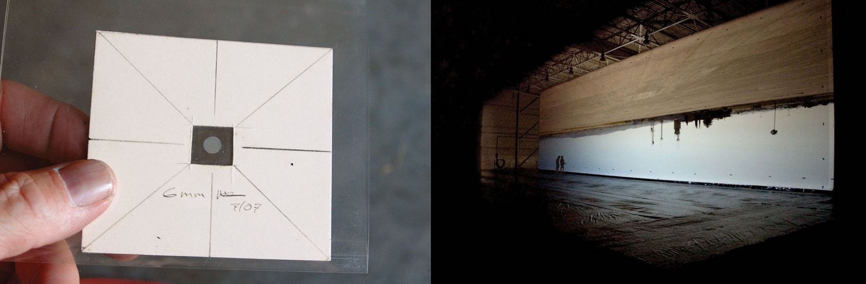
The world’s largest pinhole photograph (legacyphotoproject.com): turning a room, or even a building, into a camera obscura.
2 Field of View
How focal length affects the field of view
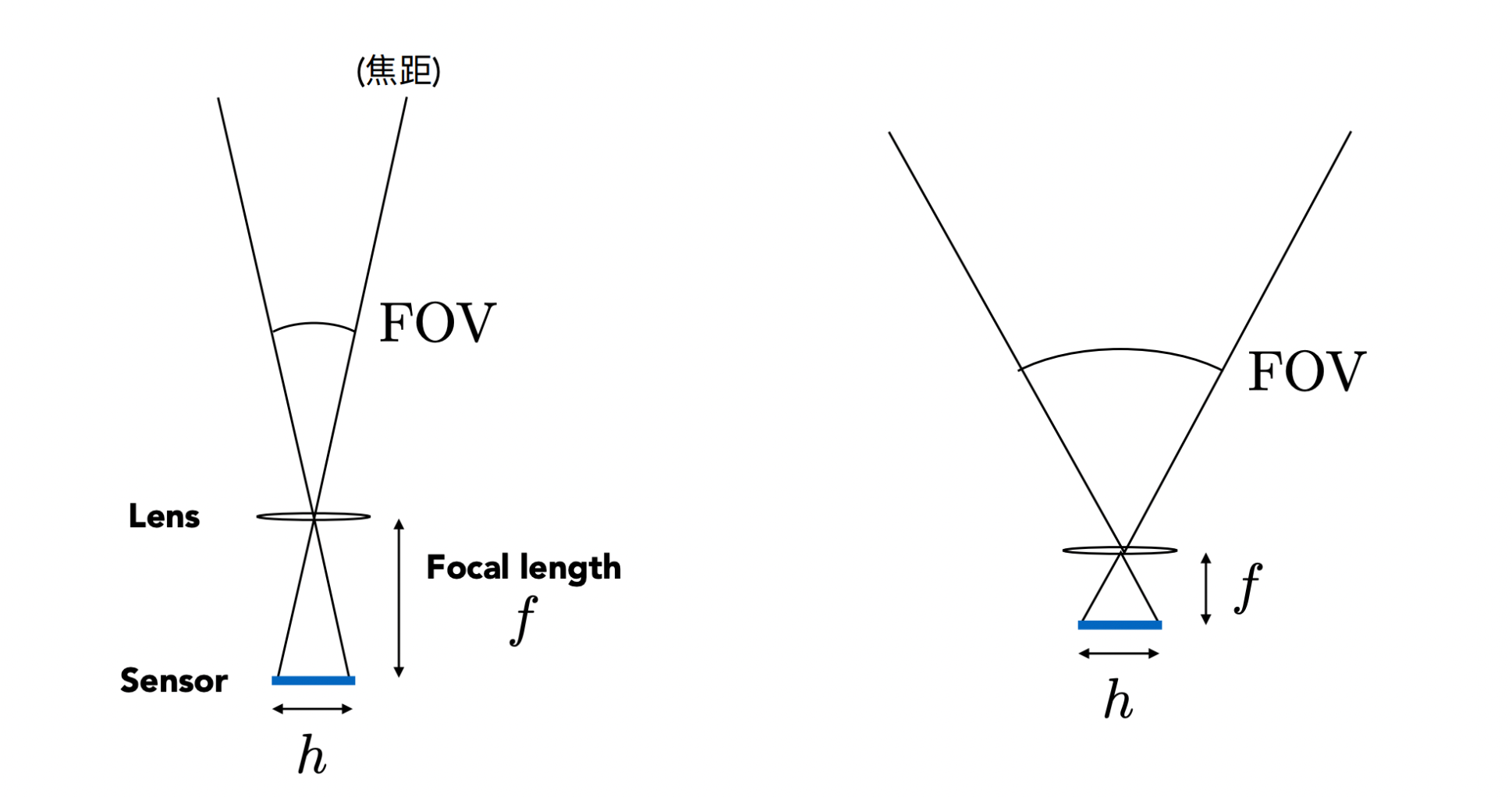
The field of view (FOV) describes how wide an angular range the camera can “see”. It is determined jointly by the sensor size $h$ and the focal length $f$:
| Symbol | Meaning |
|---|---|
| $h$ | Height (or width) of the sensor, depending on whether you want the vertical or horizontal FOV |
| $f$ | Focal length of the lens |
The conclusion: with the sensor size fixed, the smaller the focal length, the larger the field of view.
The convention for converting between focal length and FOV
For historical reasons, people are used to describing the FOV by “the focal length a lens would have on the 35mm film format (36 × 24mm)”:
| Focal length (35mm format) | Type | Field of view |
|---|---|---|
| 17mm | Wide angle | 104° |
| 50mm | Normal | 47° |
| 200mm | Telephoto | 12° |
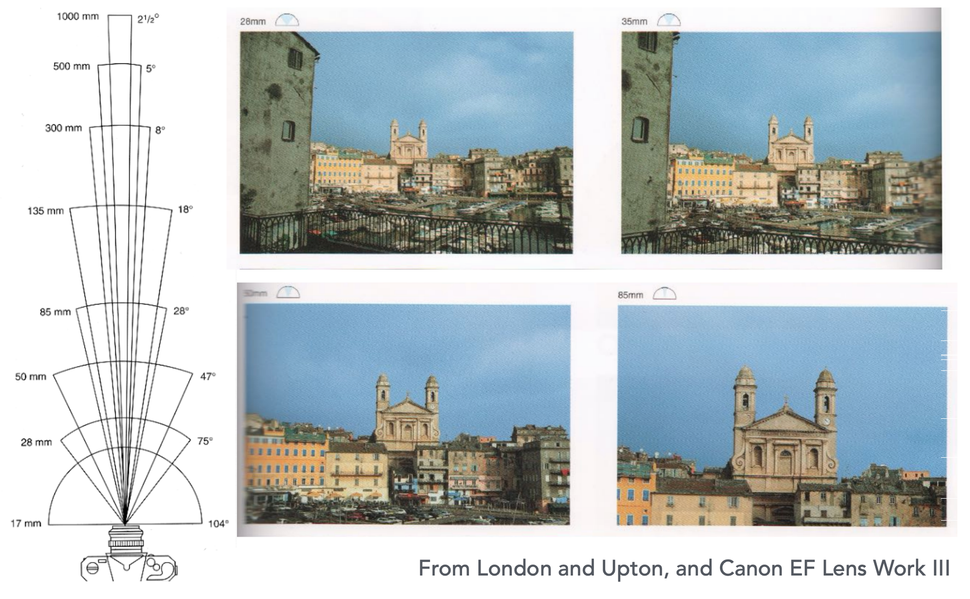
Note: when we say a modern phone is around a 28mm “equivalent” focal length, this is the convention at work — the phone sensor is far smaller than 35mm and its actual focal length is only a few millimetres; it is just that the FOV is comparable.
How sensor size affects the field of view
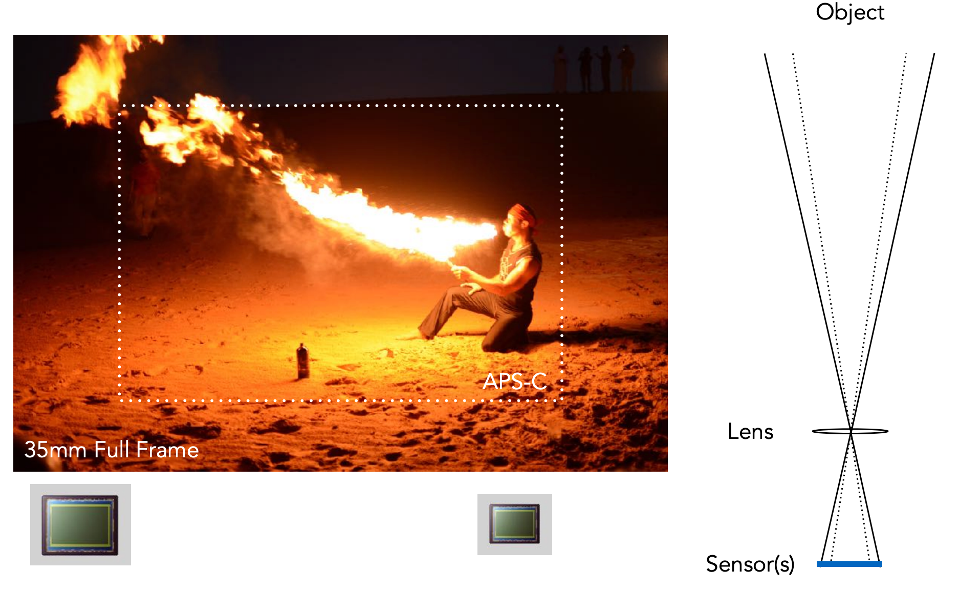
The smaller the sensor, the smaller the field of view (with the focal length held fixed).
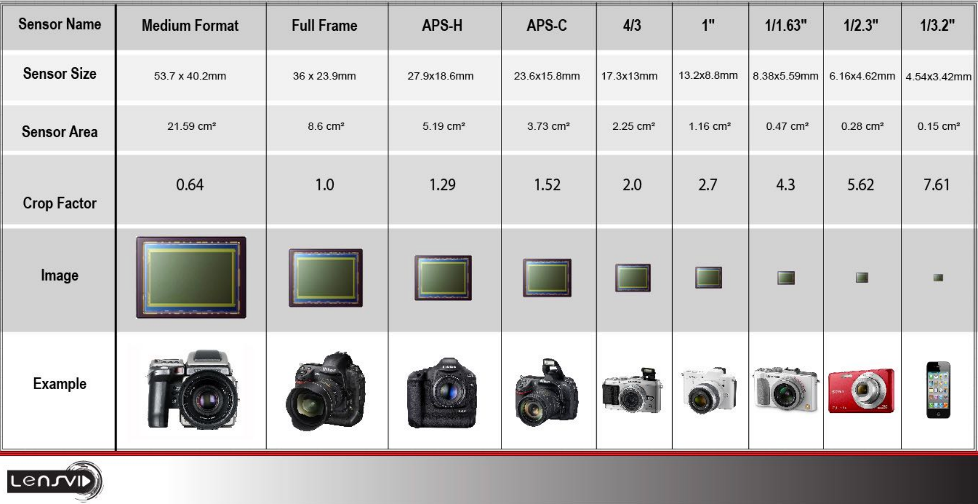
Keeping the field of view on a smaller sensor
To keep the FOV unchanged, scale the focal length down proportionally to the sensor’s width or height ratio.
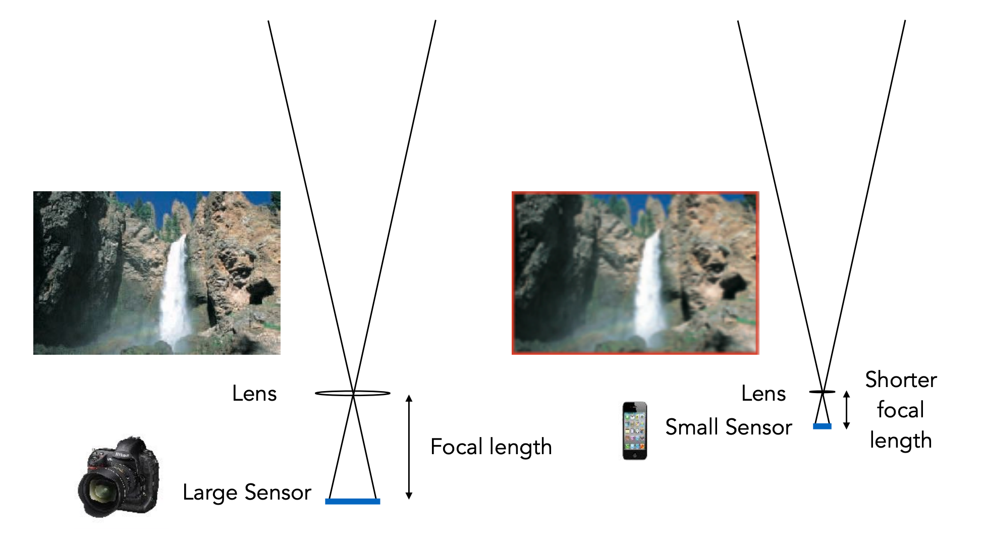
This is also why the same lens has a narrower field of view on an APS-C body (the equivalent focal length is multiplied by a crop factor of roughly 1.5).
3 Exposure
The definition of exposure
$$ H = T \times E $$Exposure = exposure time × irradiance.
| Quantity | Meaning | Controlled by |
|---|---|---|
| Exposure time $T$ | How long the sensor is exposed to light | Shutter |
| Irradiance $E$ | Optical power per unit sensor area | Aperture and focal length |
The three controls of exposure
| Control | Means |
|---|---|
| Aperture size | Change the f-stop by opening or closing the aperture (when the camera has an aperture ring) |
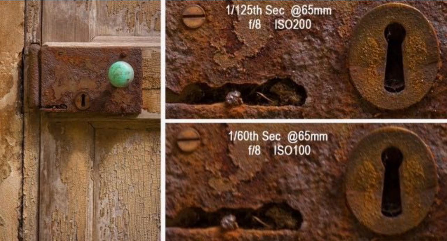
| Shutter speed | Change how long the sensor pixels accumulate light |
| ISO gain | Change the amplification factor between sensor values and digital image values (analog and/or digital) |
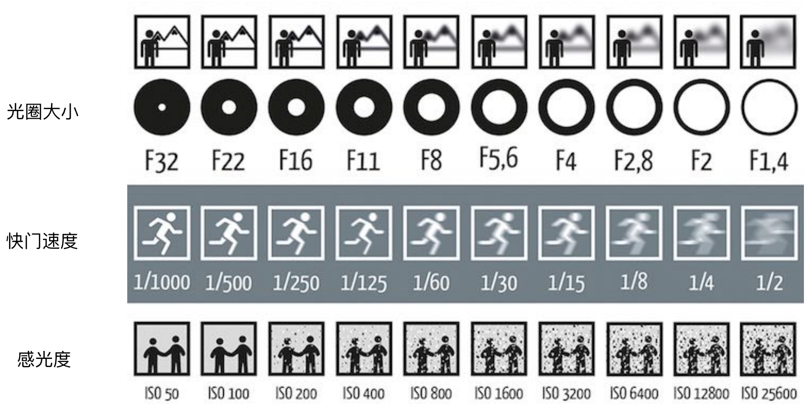
ISO (gain)
The core role of ISO is to control the camera’s amplification of the light signal, so that with aperture and shutter already decided you can still bring the photo’s brightness to a suitable level.
- It adjusts image brightness.
- The lower the ISO, the smaller the amplification, the darker the image — but usually with less noise and a wider dynamic range.
- The higher the ISO, the larger the amplification, the brighter the image — but noise and image-quality loss are usually more obvious.
- It buys exposure freedom alongside aperture and shutter. When aperture and shutter can no longer be adjusted, it provides extra exposure latitude.
- It affects image quality: noise, dynamic range, colour.
| Aspect | Low ISO | High ISO |
|---|---|---|
| Noise | Low | High |
| Dynamic range | Wide | Narrow |
| Highlight latitude | Good | Prone to clipping |
| Colour depth | Good | May degrade |
| Detail retention | Good | May be wiped out by noise reduction |
ISO is the third variable of exposure:
- Film era: trade sensitivity for grain
- Digital era: trade sensitivity for noise
- The signal is amplified before analog-to-digital conversion
- The effect is linear: ISO 200 needs only half the light that ISO 100 does
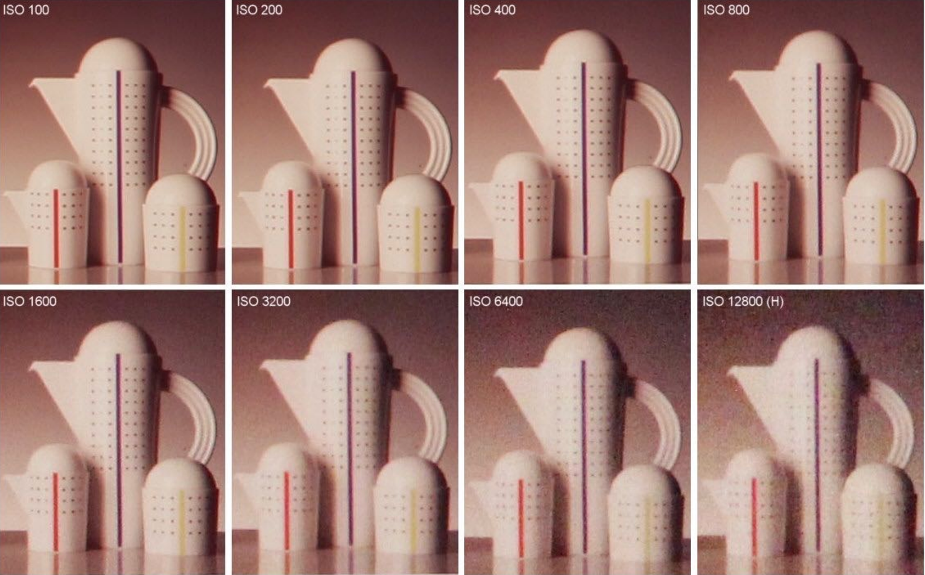
The reason ISO amplification introduces noise is essentially this: while it amplifies the signal, it also amplifies the sensor’s own inherent noise, and later digital amplification introduces additional quantization noise.
F-Number / F-Stop
Written as $F_N$ or $F/N$, where $N$ is the f-number.
- Informal reading: the reciprocal of the circular aperture’s diameter (the larger the aperture diameter, the more energy gets in)
- Formal definition: a lens’s f-number is defined as the focal length divided by the aperture diameter
| Symbol | Meaning |
|---|---|
| $f$ | Focal length |
| $D$ | Absolute diameter of the aperture |
| $N$ | f-number |
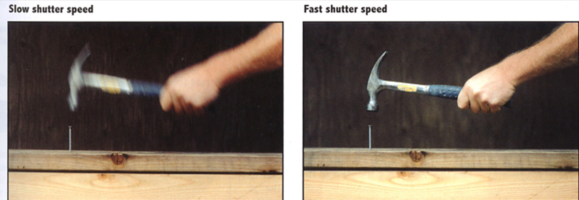
A side effect of shutter speed: motion blur
Motion blur comes from handshake and subject movement.
Double the shutter time, and you double the motion blur.
Note: motion blur is not always a bad thing. Hint: think of anti-aliasing — motion blur is essentially averaging along the time dimension, which is the same kind of operation as averaging samples within a pixel.
Rolling shutter
Different parts of the photograph were taken at different times — because the sensor is read out row by row rather than exposed all at once.

Constant exposure: trading aperture against shutter speed
The aperture / shutter combinations below all give equivalent exposure:
| F-Stop | 1.4 | 2.0 | 2.8 | 4.0 | 5.6 | 8.0 | 11.0 | 16.0 | 22.0 | 32.0 |
|---|---|---|---|---|---|---|---|---|---|---|
| Shutter | 1/500 | 1/250 | 1/125 | 1/60 | 1/30 | 1/15 | 1/8 | 1/4 | 1/2 | 1 |
If the exposure comes out too bright or too dark, you move the f-stop and/or the shutter up or down.
A photographer must trade depth of field against motion blur — this is the most central trade-off in photography.
High-speed and long-exposure photography
| Type | How it is done |
|---|---|
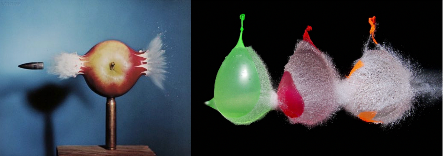
| High-speed photography | Normal exposure = a very fast shutter speed × (a large aperture and/or a high ISO). The classic work comes from Harold Edgerton |
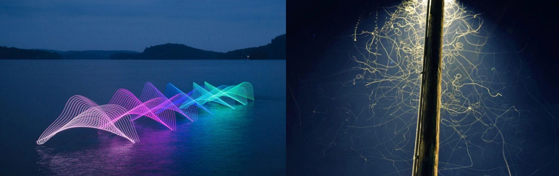
| Long-exposure photography | A very long exposure time, accumulating motion into light trails, silky water surfaces and so on |
4 Thin Lens Approximation
Real lenses are not ideal: aberrations
Real lens design is extremely complex; a high-end lens contains a dozen or so glass elements inside.
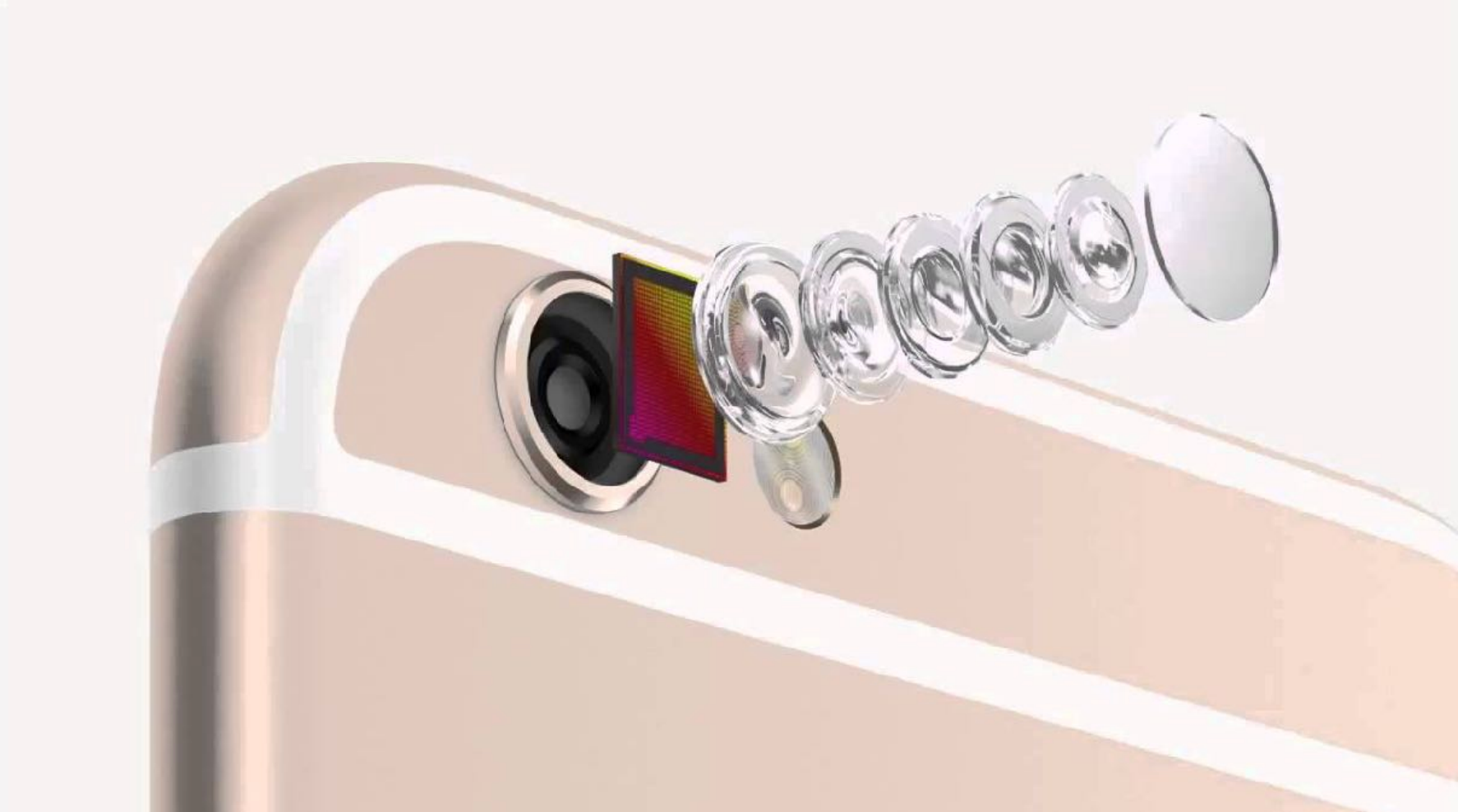
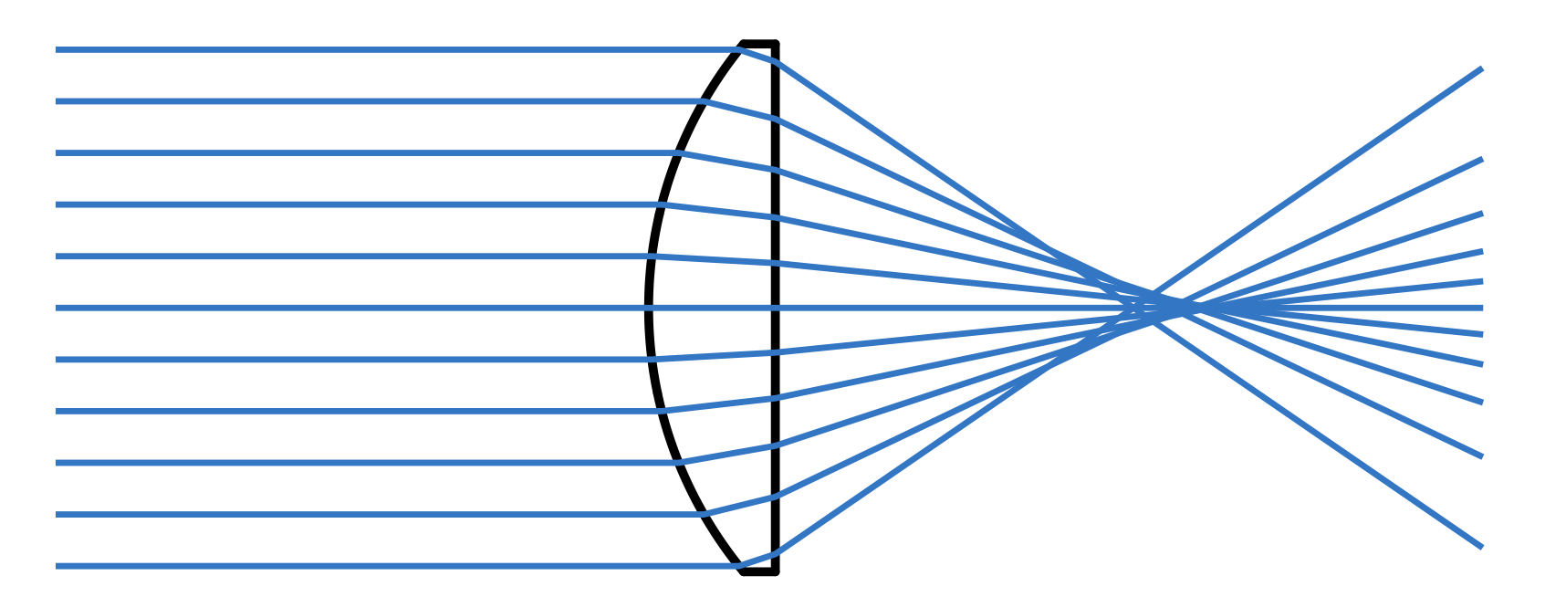
Real lens elements are not ideal — they suffer from aberration. The most typical is spherical aberration:
A real plano-convex lens (with spherical surfaces) cannot focus light to any single point.
The ideal thin lens
To be able to do the maths, we assume an idealized thin lens:
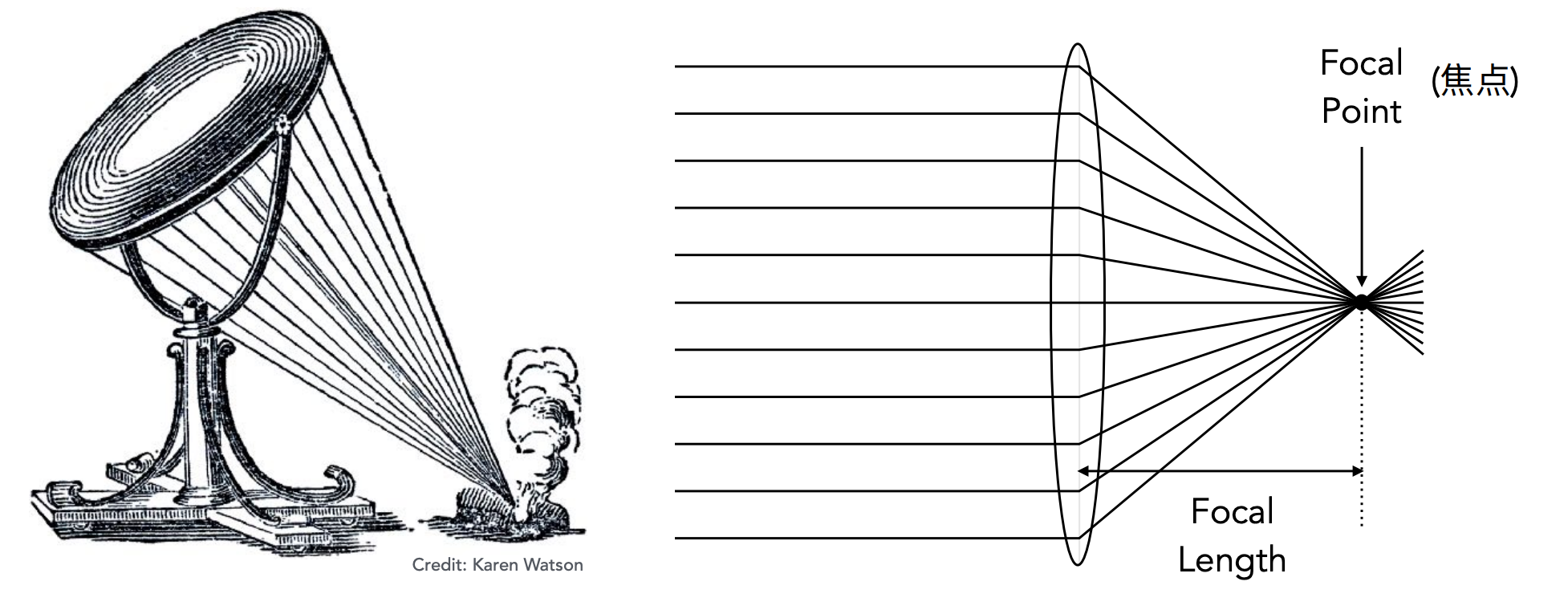
Three properties of the ideal thin lens:
- All rays entering the lens parallel to each other pass through its focal point
- All rays passing through the focal point become parallel after passing through the lens
- The focal length can be changed at will (which is indeed possible in reality — zoom lenses)
The thin lens equation
For an object distance $z_o$ (distance from the object to the lens) and an image distance $z_i$ (distance from the lens to the image plane):
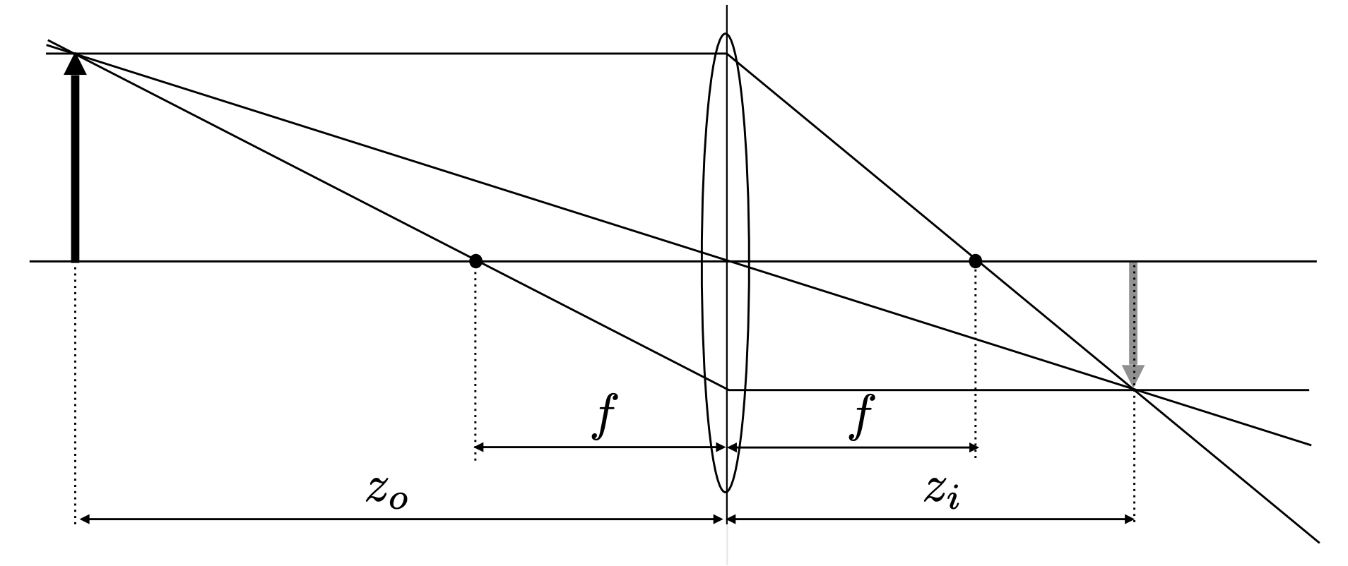
This is the Gaussian thin lens equation.
Gauss’ ray diagrams
Three special rays are enough to construct the image:
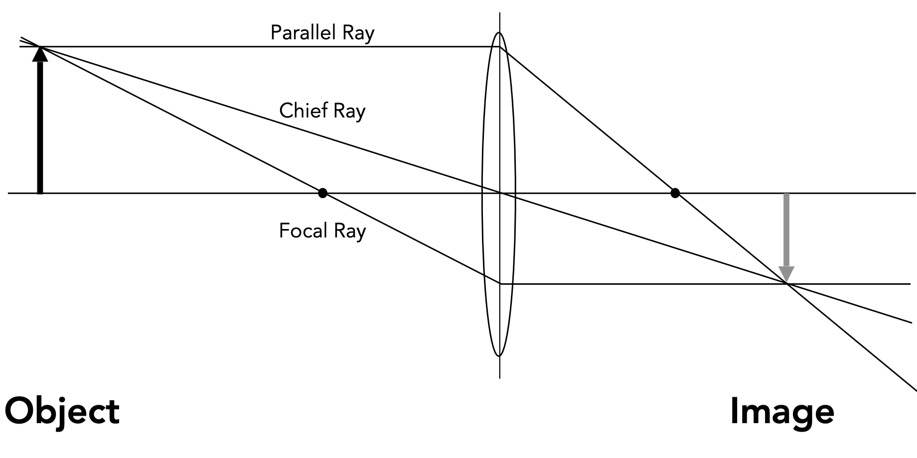
| Ray | Path |
|---|---|
| Parallel ray | Enters parallel to the optical axis → leaves through the image-side focal point |
| Chief ray | Passes through the centre of the lens → direction unchanged |
| Focal ray | Enters through the object-side focal point → leaves parallel to the optical axis |
Deriving the thin lens equation from similar triangles
Let the object height be $h_o$, the image height $h_i$, the object distance $z_o$, the image distance $z_i$ and the focal length $f$.
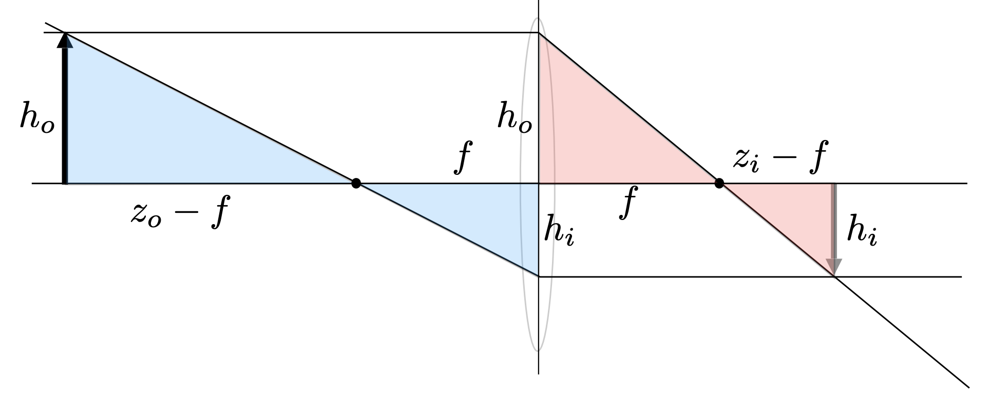
From the parallel ray (the triangle from the object-side focal point to the object apex is similar to the triangle from the image-side focal point to the image apex):
$$ \frac{h_o}{z_o - f} = \frac{h_i}{f} $$From the focal ray (the triangle from the object apex to the lens is similar to the triangle from the image apex to the image-side focal point):
$$ \frac{h_o}{f} = \frac{h_i}{z_i - f} $$Both expressions give the object-to-image height ratio $h_o / h_i$; setting them equal:
$$ \frac{z_o - f}{f} = \frac{f}{z_i - f} $$$$ (z_o - f)(z_i - f) = f^2 $$This is the Newtonian thin lens equation. Expanding the left-hand side:
$$ z_o z_i - z_o f - z_i f + f^2 = f^2 $$$$ z_o z_i = (z_o + z_i) f $$Dividing both sides by $z_o z_i f$ gives the Gaussian form:
$$ \frac{1}{f} = \frac{1}{z_i} + \frac{1}{z_o} $$5 Defocus Blur and Depth of Field
The size of the circle of confusion
When a lens focuses on some plane, only points on that plane converge perfectly to a point on the sensor. For objects off that plane, their rays converge into a blurry disc on the sensor — that disc is the circle of confusion (CoC).
- The smaller the CoC, the sharper it looks;
- The larger the CoC, the blurrier it looks;
- Once the CoC grows large enough for the human eye to notice, we call it “out of focus”.
The logic of computing depth of field is:
- First stipulate a tolerable circle-of-confusion diameter (usually written $C$);
- Find every object distance whose CoC on the sensor does not exceed $C$;
- That range is the depth of field.
So: the smaller $C$ is (the stricter the requirement), the shallower the depth of field; the larger $C$ is (the more blur allowed), the deeper the depth of field.
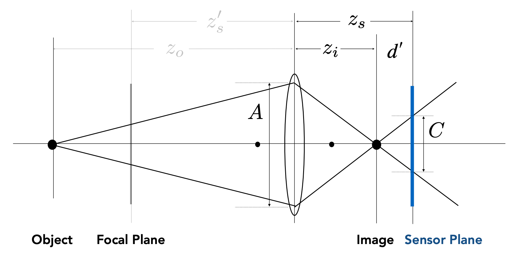
From similar triangles:
$$ \frac{C}{A} = \frac{|z_s - z_i|}{z_i} $$that is:
$$ C = A \frac{|z_s - z_i|}{z_i} $$| Symbol | Meaning |
|---|---|
| $C$ | Diameter of the circle of confusion |
| $A$ | Aperture diameter |
| $z_s$ | Distance from the observed object to the lens |
| $z_i$ | Distance from the sensor to the lens (image distance) |
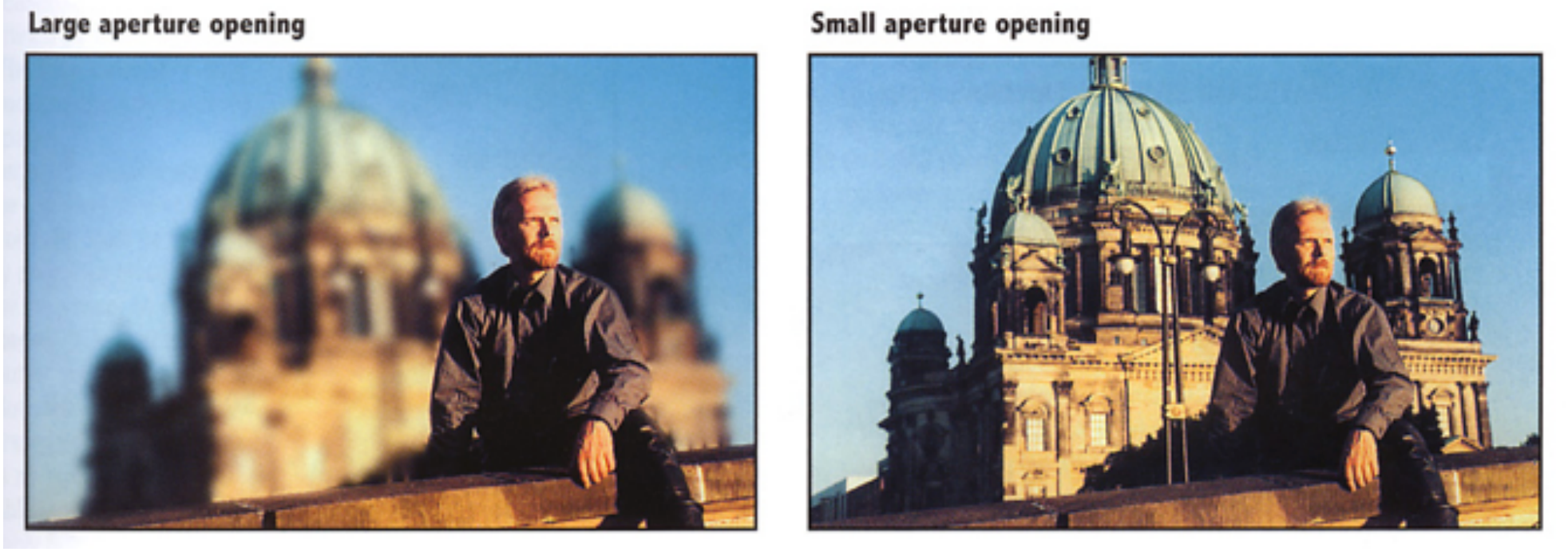
The key conclusion: the size of the circle of confusion is proportional to the size of the aperture.
Note: here the aperture diameter is written $A$, while the $D$ in the f-number formula of the previous section denotes the same quantity (the aperture diameter) — it is just a difference in notational habit between textbooks.
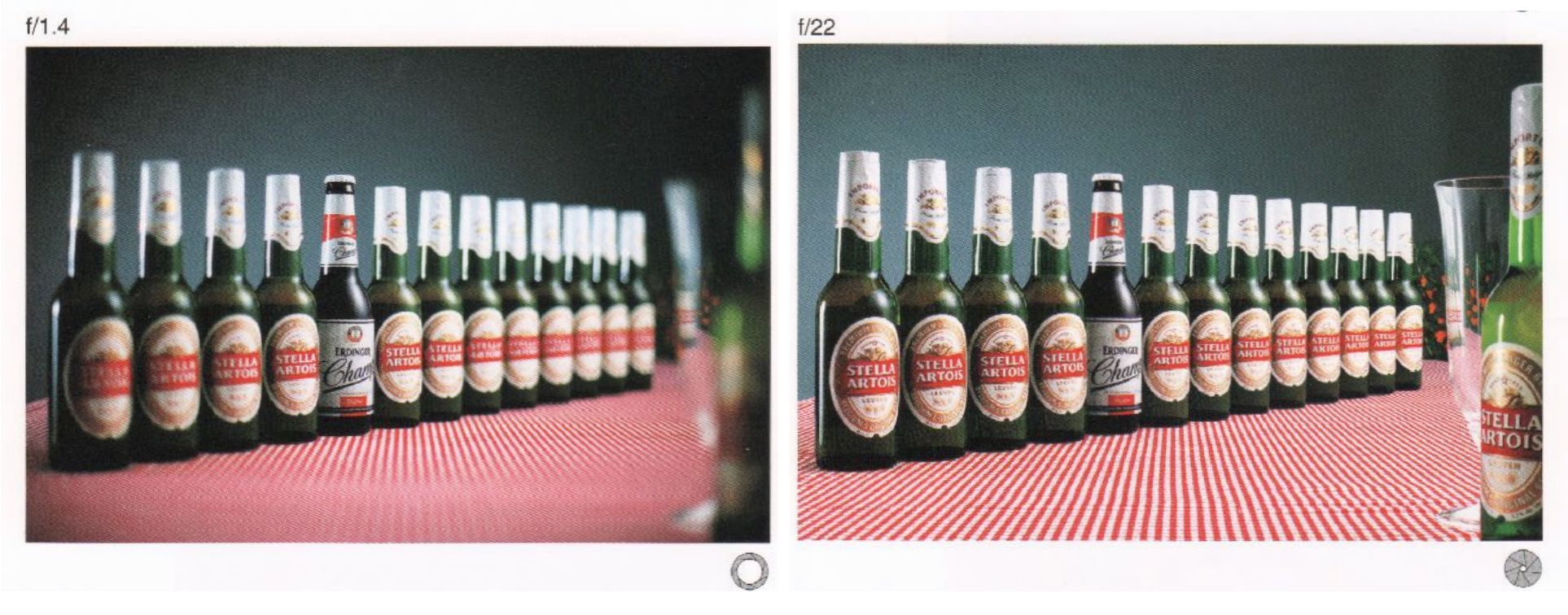
How the CoC relates to aperture size
Revisiting the f-number
- Formal definition: a lens’s f-number is defined as the focal length divided by the aperture diameter
- Common f-stops on real lenses: 1.4, 2, 2.8, 4.0, 5.6, 8, 11, 16, 22, 32
- An f-stop of 2 is sometimes written $f/2$, reflecting the fact that the absolute aperture diameter $A$ can be computed from the focal length $f$ divided by the relative aperture $N$
A worked example:
| Aperture diameter $D$ | Focal length $f$ | f-number $N = f/D$ |
|---|---|---|
| 50 mm | 100 mm | 2 |
| 100 mm | 200 mm | 2 |
| 100 mm | 400 mm | 4 |
The CoC is inversely proportional to the f-number
Substituting $A = f / N$ into the CoC formula:
$$ C = A \frac{|z_s - z_i|}{z_i} = \frac{f}{N} \cdot \frac{|z_s - z_i|}{z_i} $$So the larger the f-number (the smaller the aperture), the smaller the circle of confusion and the sharper the image. This is why “stopping down to f/16 makes things sharper”.
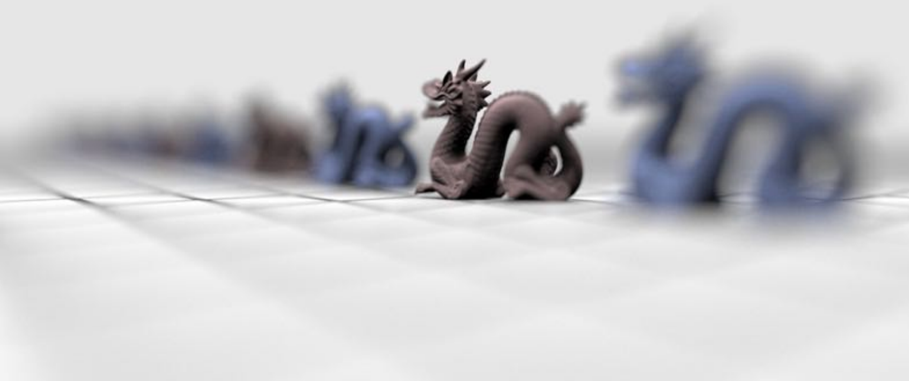
Rendering defocus blur with ray tracing
Simulating a real camera inside a renderer:
Setup:
- Choose the sensor size, the lens focal length and the aperture size
- Choose the subject depth of interest $z_o$
- Use the thin lens equation to compute the corresponding sensor depth $z_i$
Rendering:
- For each pixel $x'$ on the sensor (really on the film)
- Sample a point $x''$ randomly on the lens plane
- The ray, after passing through the lens, must hit $x'''$ (because $x'''$ lies on the focal plane — consider the virtual ray $(x', \text{lens centre})$)
- Estimate the radiance along the ray $x'' \to x'''$
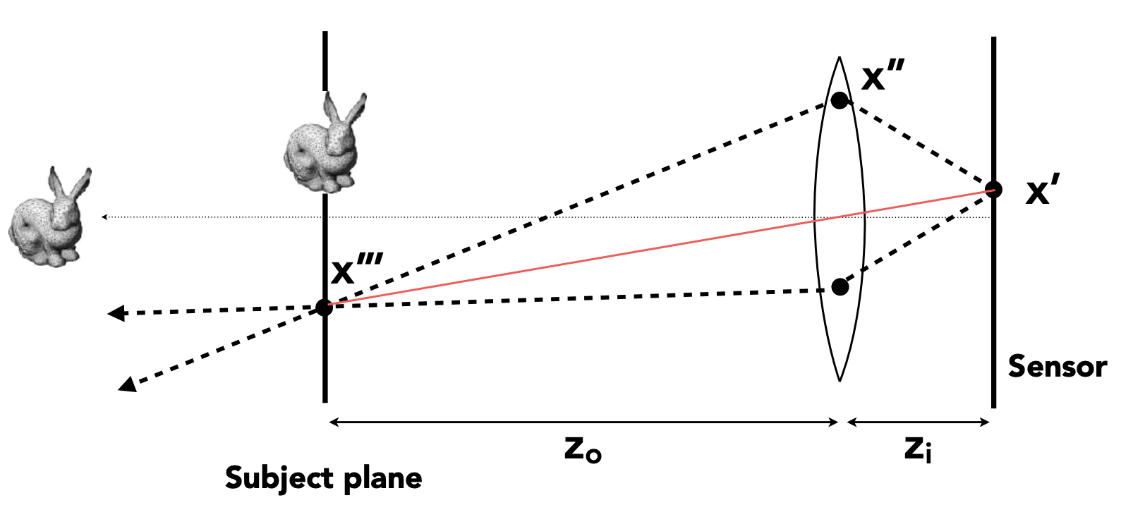
Note: this is exactly path tracing + lens sampling. Replace “the primary ray from the camera” with “a ray starting from a random point on the lens”, and defocus blur falls out naturally — no special blur post-processing required.
Depth of field
Depth of field is the range of object depths in an image that are rendered with acceptable sharpness.
The approach: set the circle of confusion to the largest blur spot that “still looks sharp under the final viewing conditions”. Any range of depths whose CoC does not exceed this threshold counts as “sharp”, and that range is the depth of field.
The quantitative depth of field formulas (FYI)
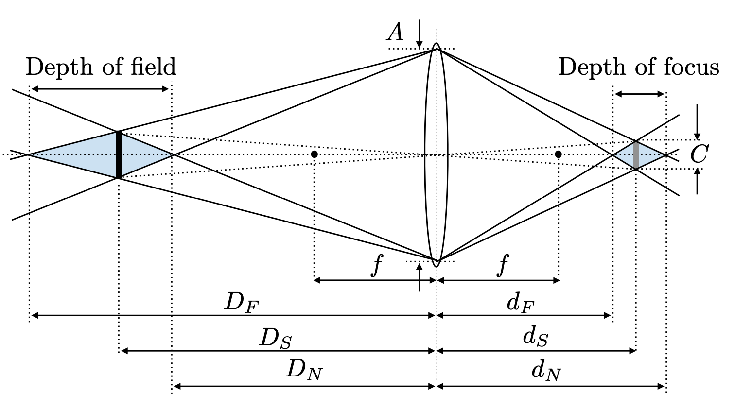
| Quantity | Meaning |
|---|---|
| $D_S$ | Subject (focus) distance |
| $D_F$ | Far limit |
| $D_N$ | Near limit |
| $C$ | Tolerable circle-of-confusion diameter |
| $N$ | f-number |
| $f$ | Focal length |
Be careful to distinguish two concepts:
| Concept | Space | Meaning |
|---|---|---|
| Depth of field | Object space | The range of depths in the scene that look sharp |
| Depth of focus | Image space | The tolerable sharpness range on the image plane |
Summary
Lecture 19 shifts the viewpoint from “generating an image” to “capturing an image”, turning the camera into a parameterizable model inside the renderer:
| Topic | Key content |
|---|---|
| Imaging = synthesis + capture | Rasterization / ray tracing are synthesis, the camera is capture; both end up as irradiance on the sensor |
| Why a lens is needed | The sensor records irradiance and inherently loses direction; you must filter direction with a pinhole or lens to form an image |
| Field of view | $\text{FOV} = 2\arctan(h / 2f)$; a smaller focal length gives a wider FOV, a smaller sensor gives a narrower one |
| Exposure | $H = T \times E$, jointly controlled by aperture, shutter speed and ISO |
| ISO | Amplifies the signal before analog-to-digital conversion, linear gain; the cost is amplified noise and a compressed dynamic range |
| f-number | $N = f / D$; adjacent f-stops differ by a factor of $\sqrt{2}$ and combine with shutter speed to give equivalent exposures |
| Thin lens | Three properties plus the Gaussian equation $1/f = 1/z_i + 1/z_o$ (Newtonian form $(z_o - f)(z_i - f) = f^2$) |
| Circle of confusion | $C = A, |
| Rendering defocus blur | Path tracing plus random sampling on the lens plane, with no special blur post-processing |
| Depth of field / depth of focus | Depth of field lives in object space (the range of scene depths that look sharp), depth of focus in image space (the sharp range on the image plane) |
This post is note #10 in the GAMES101 - Modern Computer Graphics learning series.